cnc milling
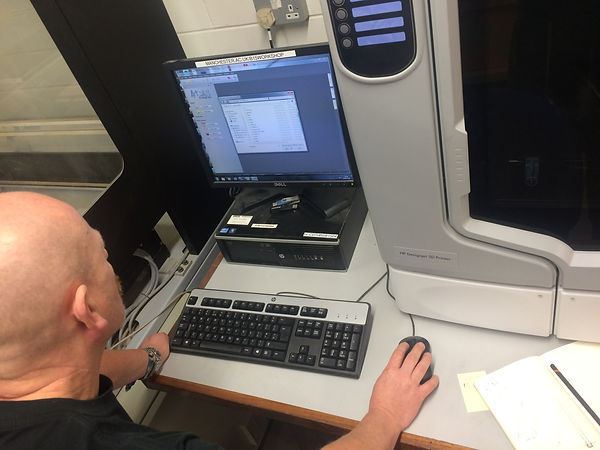
We decided to create the stone wall using an attractive wood which could be milled on a CNC machine to recreate the curvaceous profile. We decided to use mahogany because of its quality and rich colour. The main task was to computer model the wall section and create a 3DS file which could be milled. I used Rhino to complete this task. It was important to be as efficient with the wood as possible because the CNC machine does not create off cuts.
I had not used Rhino, or the CNC machine before and so I wanted to use this opportunity to learn these techniques.

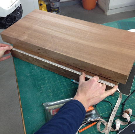
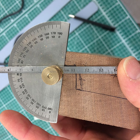
I managed to design a section through the wood which would create the least amount of wasted material. It was discussed with Jim that not every section would be successful in the machine due to being too small. We decided that the bottom section could be hand crafted.
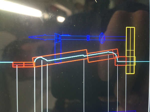
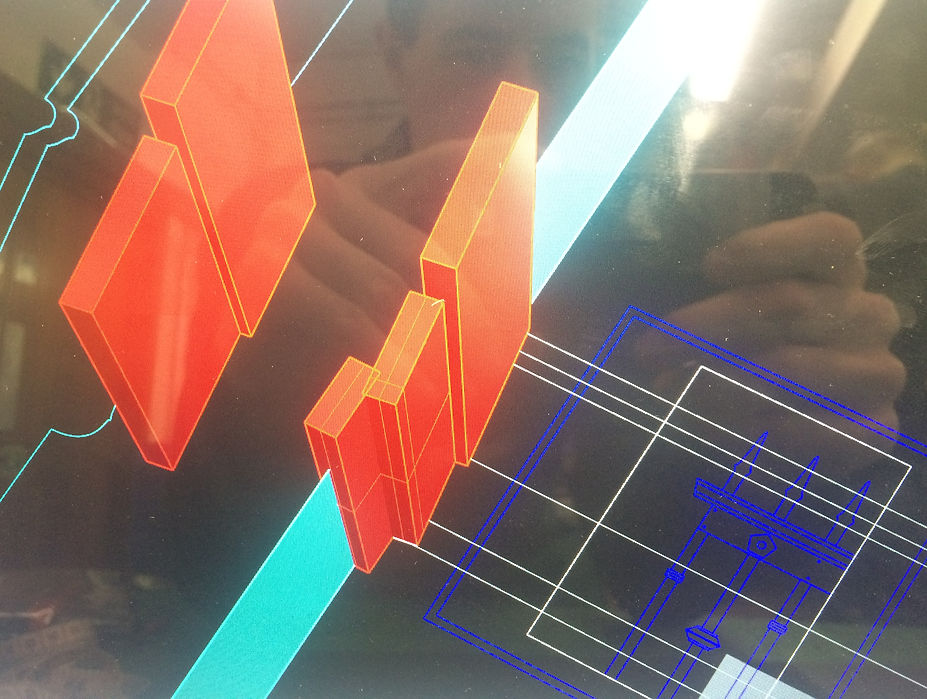
The red boxes indicate the section of wood. The white line represents the wall profile. The numbers indicate which wood element I am talking about.
1
2
3
4
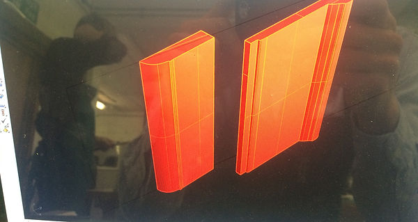
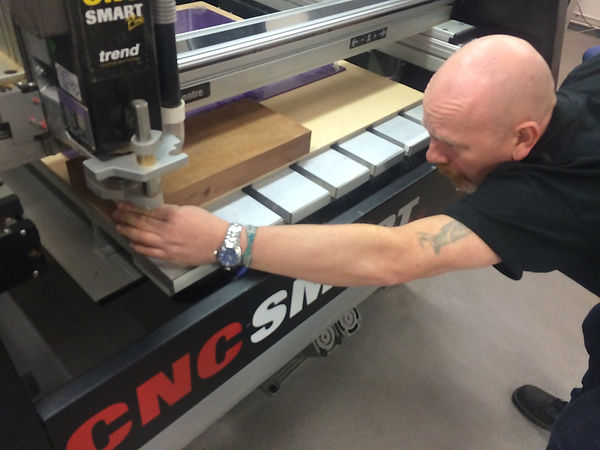
I started with piece number 3. Jim (technology tutor) helped with the setting up of the file and initiating the CNC machine. I had not used Rhino before and I used online tutorials to learn how to set up the correct file.


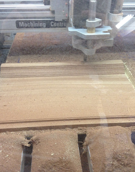
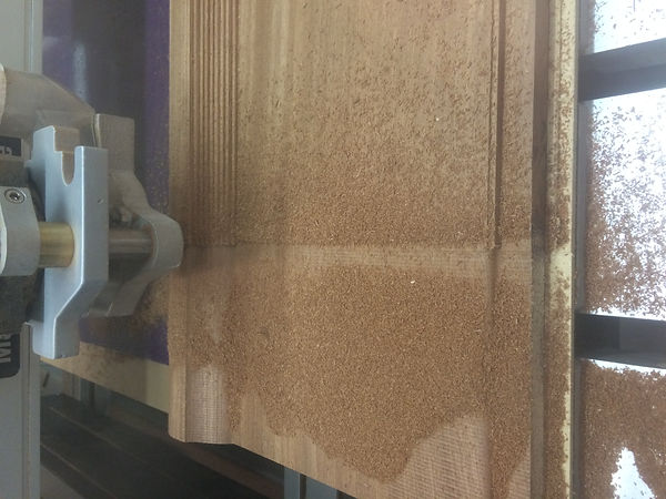
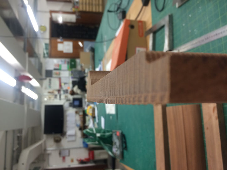
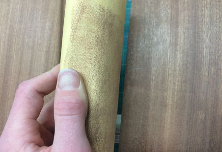
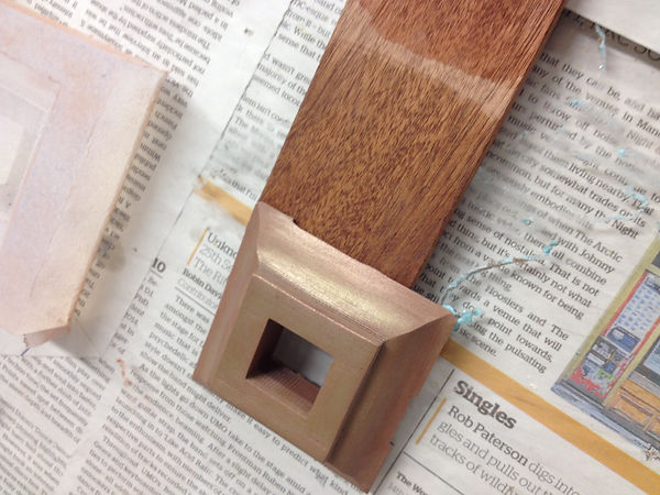
The milling of the wood leaves grooves in the wood. It was my job to sand the wood to make it smooth, reveal the grain and contours. It was necessary to use different grades of sand paper for this job. I used a low grade to remove the rough milled divots and then used higher and higher grades to create a smooth to touch finish.
The first CNC piece (piece 3) cut a 10mm margin around the edge of the form. This was a mistake. It did not cause problems for the model, however for the second piece (piece 2) it was important that the edges joined perfectly. We decided to adjust the position of the wood on the bed instead of adjusting the file. We cut the piece with all settings the same and it came out without any cut margins.


Piece number 4 formed part of the curve on the underside of the wall. It was decided to be carved by hand. I asked the technical support to cut the long section of the wood on the circular saw. They helped with guidance on how to construct this piece. The plan was to make it in two pieces.


I decided to sand the curve roughly to the curvature of the piece on the belt sander. Subsequently I hand sanded the piece to adjust the curve to the piece 3.

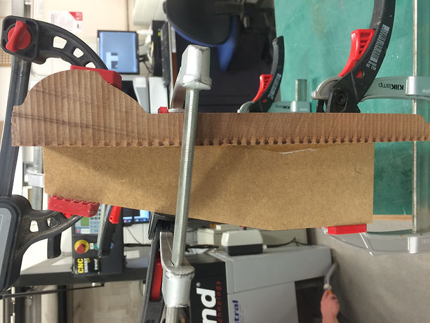
Piece number 2 started to warp. The mahogany we used has a natural tendancy to warp slightly due to its moisture content. As a result when we excavated it on the CNC machine and reduced its thickness, it started to warp.
I used straight pieces of MDF wood to provide a support frame which would bend it back to being flat. I used clamps and wood glue to secure the structure.

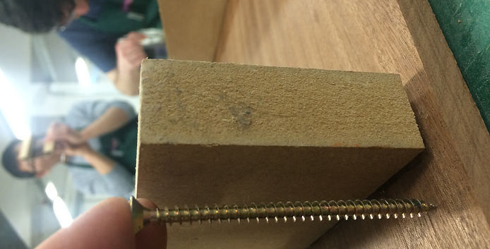
After the glue was dry I removed the clamps. The wood had partially stuck but the edges were still warping. I used screws to re-secure the wood and bond it more permanently. It was important that the screws were the right length so that they did not pierce the other side of the wood.


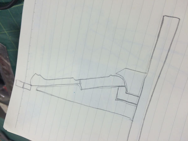
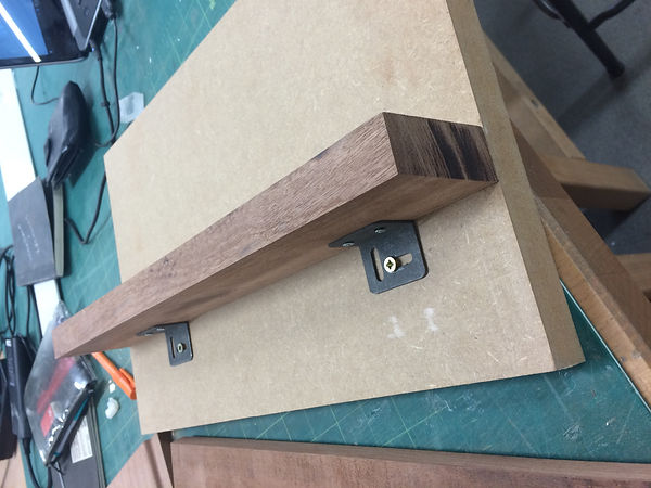
I sketched out my plan for creating the structure which would support all four pieces of wood. I used the CAD dimensions to draw out the structure on a piece of wood which I subsequently cut on the band saw.
I designed the structure so that it could be dismantled because we planned to treat the wood with a stain. For this I used screws and L brackets to make mechanical joins.


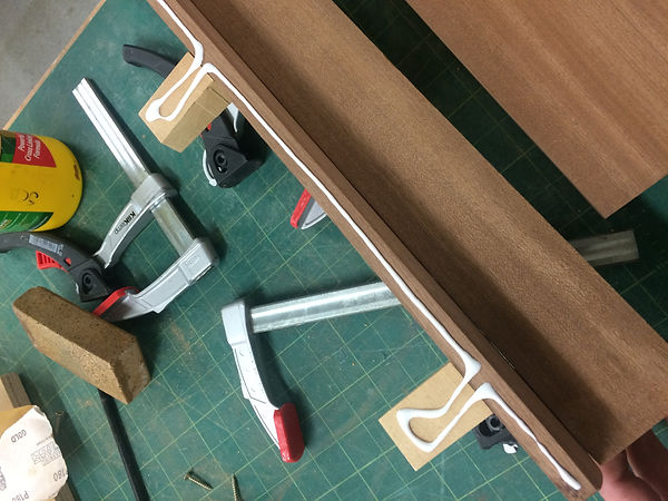

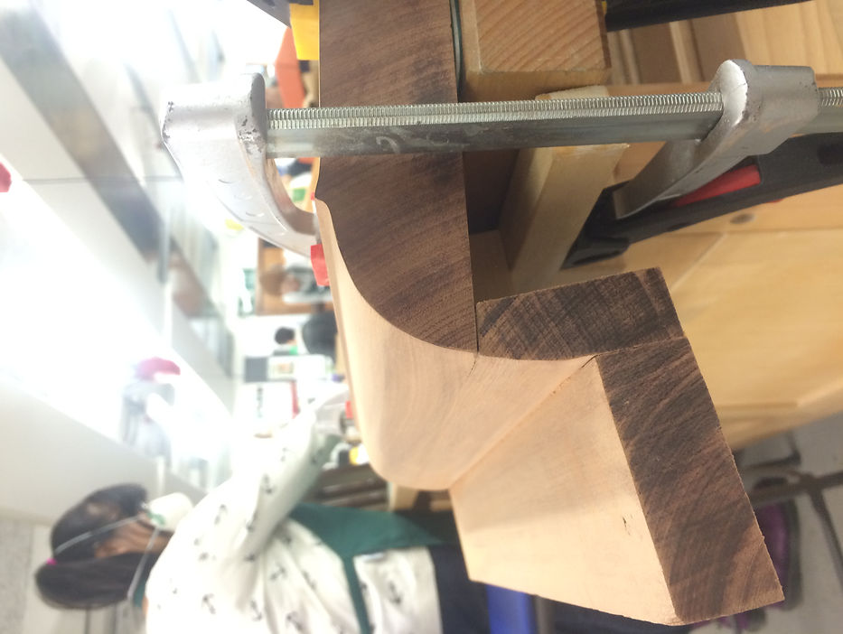
I used wood adhesive to join the two curved pieces. It was a difficult bond to clamp because of the curved profile. I used a strip of wood to reach into the required place ensuring a strong bond.
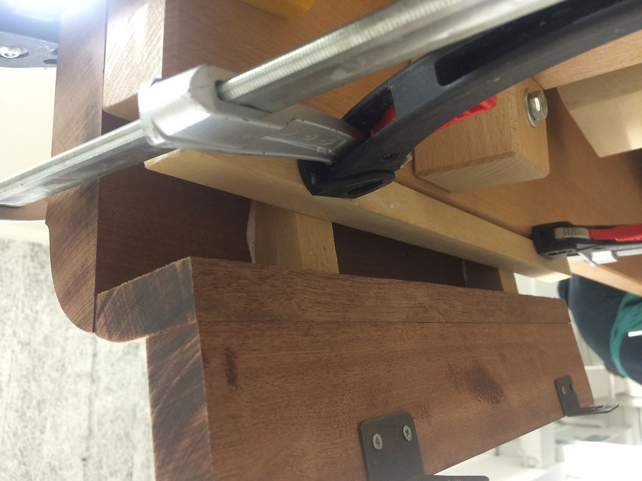
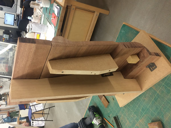
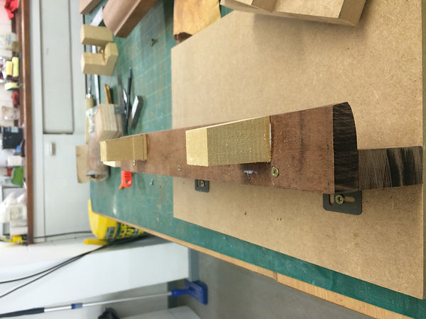
The structure allowed me to test the precision of the joins without bonding them permanently. It was important that the intersection between the wood pieces was as precise as possible because it would be visible on the front face. I used machine and hand techniques to ensure the wood had a tight join.
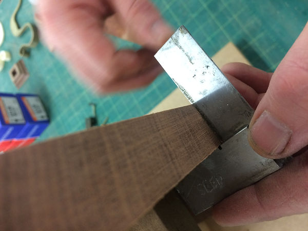
Jim showed me how to use a carpenters square to judge the straightness of the side.
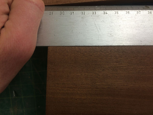
It was required that the edges were cleaned up. One edge was 3mm wide. Originally we thought that it could be cut on the circular saw, however on futher thought Jim thought it may cause undesireable splinters. We decided to try it on the belt sander. This worked.
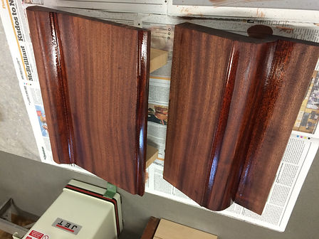
This shows how an understanding of the properties of the material can help guide which process to use. Wood is an imperfect material and it requires understanding its strengths and weaknesses to get the best results.


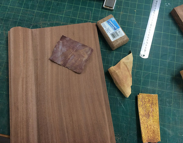
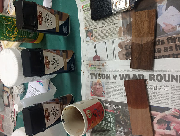
I made test pieces of mahogany to test different stains. We used these to judge the colour combination with the test pieces of metallic cast resin. The technique for stains wood requires a clean and sanded surface and then to apply even strokes lengthways to the grain.
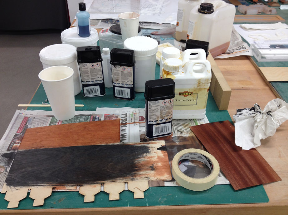

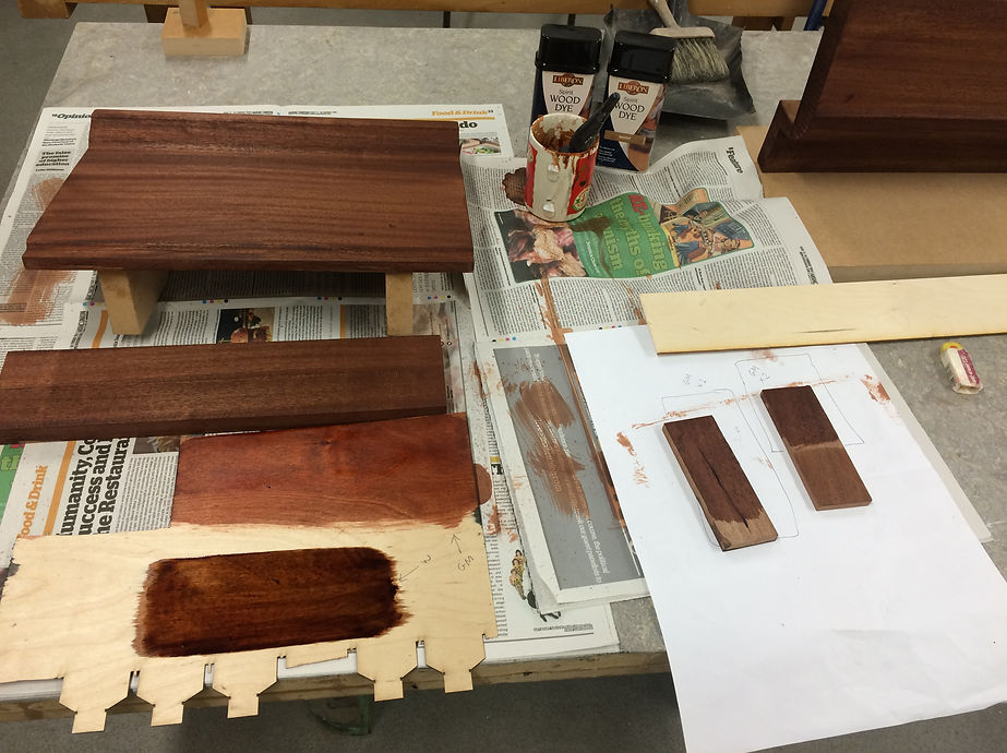

We decided to use 0.8 mm ply for the edges so that it showed a minimal amount of material on the face. I tested out densities of stain on the ply to see how much was required to match the mahogany. Before making a decision it was important to leave to dry fully over night. I made different test pieces with different intensities of coat.
We had a discussion about the base of the model and how to treat it. Being the base and not on the original building, we wanted the final item to be read as a separate element and distinctly separate from the model. The MDF board that we were currently using to construct the model did not suit the overall aesthetic of authentic materials.
After discussion of painting or covering we decided to replace the base with a thick piece of ply with an attractive grain. The ply had a distinctly different tone but looked harmonious overall because of its textural relationship with the mahogany.